Showing posts with label SOIL MECHANICS. Show all posts

Wednesday, 1 July 2015

Characteristic strength of concrete

Characteristic strength of concrete is one of the important properties of concrete which indeed unanimously by design engineeror any other person involved in the construction sector.
The compressive strength of concrete is given in terms of the characteristic compressive strength of 150 mm size cubes tested at 28 days (fck)- as per Indian Standards (ACI standards use cylinder of diameter 150 mm and height 300 mm). The characteristic strength is defined as the strength of the concrete below which not more than 5% of the test results are expected to fall.
This concept assumes a normal distribution of the strengths of the samples of concrete.
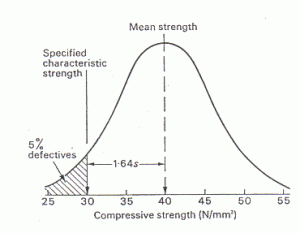
                               Normal Distribution curve on test specimens for determining compressive strength

Normal Distribution curve on test specimens for      determining compressive strength
The above sketch shows an idealized distribution of the values of compressive strength for a certain number of test specimens. The horizontal axis represents the values of compressive strength in MPa. The vertical axis represents the number of test samples for a
particular compressive strength. This is also termed as frequency.

The average of the values of compressive strength (mean strength) from the graph is 40 MPa. The characteristic strength (fck) is the value in the x-axis below which 5% of the total area under the curve falls. From the graph we can clearly say that 30 MPa is the characteristic strength of the given concrete mix. The value of fck is lower than fcm (40 MPa- mean strength) by 1.64σ, where σ is the standard deviation of the normal distribution.
So we can say the given concrete mix has a characteristic strength of 30 MPa or it is a M30 grade mix.
   M- Mix
* Note: For a 95% confidence level k=1.64 , hence k value varies on the confidence level of the experiment
Definition:
Characteristic strength of concrete is the strength of concrete specimens casted and tested as per given code of practice and cured for a period of 28 days; 95% of tested cubes should not have a value less than this value.

About piles

End Bearing Piles ::-

1:-In end bearing piles, the bottom end of the pile rests on a layer of especially strong soil or rock.
2:- The load of the building is transferred through the pile onto the strong layer.
3:-In a sense, this pile acts like a column.
4:-The key principle is that the bottom end rests on the surface which is the intersection of a weak and strong layer. The load therefore bypasses the weak layer and is safely transferred to the strong layer.


Friction Piles ::-

1:-Friction piles work on a different principle.
2:- The pile transfers the load of the building to the soil across the full height of the pile, by friction.
3:-In other words, the entire surface of the pile, which is cylindrical in shape, works to transfer the forces to the soil.


NOTE: In practice, however, each pile resists load by a combination of end bearing and friction

Tuesday, 30 June 2015

POINTS TO REMEMBER FOR CIVIL SITE ENGINEERS

Following are few general points to remember for civil site engineers to make the construction work easier while maintaining quality of construction.
  • Lapping is not allowed for the bars having diameters more than 36 mm.
  • Chair spacing maximum spacing is 1.00 m (or) 1 No per 1m2.
  • For dowels rod minimum of 12 mm diameter should be used.
  • Chairs minimum of 12 mm diameter bars to be used.
  • Longitudinal reinforcement not less than 0.8% and more than 6% of gross C/S.
  • Minimum bars for square column is 4 No’s and 6 No’s for circular column.
  • Main bars in the slabs shall not be less than 8 mm (HYSD) or 10 mm (Plain bars) and the distributors not less than 8 mm and not more than 1/8 of slab thickness.
  • Minimum thickness of slab is 125 mm.
  • Dimension tolerance for cubes + 2 mm.
  • Free fall of concrete is allowed maximum to 1.50m.
  • Lap slices not be used for bar larger than 36 mm.
  • Water absorption of bricks should not be more than 15 %.
  • PH value of the water should not be less than 6.
  • Compressive strength of Bricks is 3.5 N / mm2.
  • In steel reinforcement binding wire required is 8 kg per MT.
  • In soil filling as per IS code, 3 samples should be taken for core cutting test for every 100m2.

Density of Materials:

Material
Density
Bricks
1600 – 1920 kg/m3
Concrete block
1920 kg/ m3
Reinforced concrete
2310 – 2700 kg/ m3

Curing time of RCC Members for different types of cement:

Super Sulphate cement: 7 days
Ordinary Portland cement OPC: 10 days
Minerals & Admixture added cement: 14 days

De-Shuttering time of different RCC Members

RCC Member
De-shuttering time
For columns, walls, vertical form works
16-24 hrs.
Soffit formwork to slabs
3 days (props to be refixed after removal)
Soffit to beams props
7 days (props to refixed after removal)
Beams spanning upto 4.5m
7 days
Beams spanning over 4.5m
14 days
Arches spanning up to 6m
14 days
Arches spanning over 6m
21 days

Cube samples required for different quantity of concrete:

Quantity of Concrete
No. of cubes required
1 – 5 m3
1 No’s
6 0 15 m3
2 No’s
16 – 30 m3
3 No’s
31 – 50 m3
4 No’s
Above 50 m3
4 + 1 No’s of addition of each 50 m3

Sunday, 10 May 2015

Rollers

Rollers are the construction equipment used for the compaction of soil, gravel, sand, crushed stone layers, etc.  Roller working principle is based on vibration, impact loading, kneading and by applying direct pressure on the respective layer. The four most commonly used rollers are;
  1. Vibratory Roller
  2. Tamping roller/ sheep foot rolle
  3. Smooth wheel rollers
  4. Pneumatic tired roller

VIBRATORY ROLLER

Vibratory type rollers have two smooth wheels/ drums plus the vibrators. One is fixed at the front and the other one is on the rear side of vibratory roller. Both wheels/drums are of the same diameter, length and also of same weight. Vibratory roller covers the full area under wheel. To make vibratory roller more efficient, vibrators are also fixed with smooth wheel rollers. Vibration of vibrators arrange the particles by first disturbing even the arranged ones. On the other hand weight of wheels exerts direct pressure on the layer. Vibrators are turned off during the reversed motion of roller. In that time only static weight directly acts on the soil layer.
Vibration is to reduce the air voids and to cause densification of granular soils. During vibration of soil layer,  rearrangement of particles occurs due to deformation of the granular soil because of oscillation of the roller in a cycle.
Vibratory Roller

SHEEP FOOT ROLLER/ TAMPING ROLLER

Sheep foot roller also named tamping roller. Front steel drum of sheep foot roller consists of many rectangular shaped boots of equal sizes fixed in a hexagonal pattern. Coverage area of sheep foot roller is less i.e., about 8- 12% because of the boots on drums. Sheep foot roller done compaction by static weight and kneading of respective layer. This makes tamping roller better suited for clay soils. Contact pressure of sheep foot roller varies from 1200- 7000Kpa.
Sheep Foot Roller
Tamping foot roller consists of four wheels and on each wheel kneading boots/feet are fixed. Tamping roller has more coverage area i.e., about 40- 50%. Contact pressure of tamping roller varies from 1400 – 8500KPa. It is best dedicated for fine grained soils.
Tamping Roller differs from sheep foot roller by its wheel type.

SMOOTH WHEEL ROLLER

Smooth wheel roller and vibratory rollers are the same. Both have the same characteristics. Only the difference in both is vibratory equipment. Smooth wheel roller has no vibrator attached with the drum. This makes smooth wheel roller best suited for rolling of weaker aggregates, proof rolling of subgrades and in compacting asphalt pavements. Compaction of clay or sand is not a good choice to done with smooth wheel roller. This is so, because there are many empty voids in clay soil and sand, which cannot be minimized without vibrators.
Smooth wheel roller

PNEUMATIC TIRED ROLLER

Pneumatic tired roller has a number of rubber tires at the front and at the rear end.  Empty spaces left in between the two tires that make 80% coverage area under the wheels. Pneumatic roller has the ability to exert contact pressure ranges from 500 – 700Kpa. Pneumatic tired roller can be used for highways, construction of dams and for both fine grained and non-cohesive soils. It is also used for smoothening of finishing bitumen layer on highways, roads, streets etc.

Monday, 28 October 2013

method of ground improvement for a particular object will depend on==>>

Suitability, Feasibility and Desirability==>>

The choice of a method of ground improvement for a particular object will depend on the following factors.
● Type and degree of improvement required
● Type of soil , geological structure, seepage conditions
●cost
● Availability of equipment and materials and the quality of work required
● Construction time available
● Possible damage to adjacent structures or pollution of ground water resources
● Durability of material involved ( as related to the expected life of structure for a given environmental and stress conditions)
● Toxicity or corrosivity of any chemical additives .
● Reliability of method of analysis and design.
● Feasibility of construction control and performance measurements
If soil is moist, freezing is applicable to all type of soil

Saturday, 21 September 2013

==>>Effective/total stress in soil

Effective/total stress in soil

Vertical normal stress σz is defined as:
where: σz - vertical normal total stress
γef - submerged unit weight of soil
z - depth bellow the ground surface
γw - unit weight of water
This expression in its generalized form describes so called concept of effective stress:
where: σ - total stress (overall)
σef - effective stress (active)
u - neutral stress (pore water pressure)
Total, effective and neutral stress in the soilTotal, effective and neutral stress in the soil
Effective stress concept is valid only for the normal stress  σ, since the shear stress τ is not transferred by the water so that it is effective. The total stress is determined using the basic tools of theoretical mechanics, the effective stress is then determined as a difference between the total stress and neutral (pore) pressure (i.e. always by calculation, it can never be measured). Pore pressures are determined using laboratory or in-situ testing or by calculation. To decide whether to use the total or effective stresses is no simple. The following table may provide some general recommendations valid for majority of cases. We should realize that the total stress depends on the way the soil is loaded by its self weight and external effects. As for the pore pressure we assume that for flowing pore water the pore equals to hydrodynamic pressure and to hydrostatic pressure otherwise. For partial saturated soils with higher degree of it is necessary to account for the fact that the pore pressure evolves both in water and air bubbles.
Assume conditions Drained layer Undrained layer
short – term effective stress total stress
long – term effective stress effective stress
In layered subsoil with different unit weight of soils in individual horizontal layers the vertical total stress is determined as a sum of weight of all layers above the investigated point and the pore pressure:
where: σz - vertical normal total stress
γ - unit weight of soil
- unit weight of soil in natural state for soils above the GWT and dry layers
- unit weight of soil below water in other cases
d - depth of the ground water table below the ground surface
z - depth bellow the ground surface
γw - unit weight of water

Get Posts In Your Inbox