Showing posts with label STRUCTURE ANALYSIS. Show all posts

Sunday 9 April 2017

Interviews and Exams questions : ALL About Cement


1: Name the component that responsible for early strength of concrete:

Ans: C3S ( Tri Calcium silicate ) , that react with water and produces more heat of hydration is responsible for early strength of concrete.


2: Which compound contribute to the later strength of concrete ?
Ans: C2S ( Di Calcium silicate ) that hydrates slowly , contribute to the later strength of concrete .


3: After how many days , the compressive strength developed by C3S and C2S are equal .
Ans: ONE year  

4:For road rapid work which type of cement is recommended :
Ans: Rapid hardening cement

5: In how many  days , about 50% of the total heat evolution occurs.
Ans: During the first 3 days of hydration 

6:Which oxides are responsible for high early strength of cement ?
Ans: High total alumina and high ferric oxide content favour the production of high early strength in cement


Compounds : When components of cements added up with water than they called compound in simple language ..


Tricalcium Silicate (C3S) hardens rapidly and is largely responsible for initial set and early strength.


In general, the early strength of portland cement concrete is higher with increased percentages of C3S.


Dicalcium Silicate (C2S) hardens slowly and contributes largely to strength increases at ages beyond 7 days.


Tricalcium Aluminate (C3A) liberates a large amount of heat during the first few days of hardening and, together with C3S and C2S may somewhat increase the early strength of the hardening cement (this effect being due to the considerable heat of hydration that this compound evolves). It does affect set times.


Tetracalcium Aluminoferrite (C4AF) contributes very slightly to strength gain. However, acts as
a flux during manufacturing. Contributes to the color effects that makes cement gray.aakes cement gray.

Compounds by percentage :


Role of compounds on properties of cement : MOST IMP


Civil Engineering Competitive Exams Books :For GATE Aspirants :1: http://amzn.to/2A4iy9K 
2: http://amzn.to/2hqwfrR ( more preferably)For SSC JE Aspirants :1: http://amzn.to/2hqwfrR
2: http://amzn.to/2z7CGtm ( Highest rated book for SSC JE)
3: http://amzn.to/2iOjtqm

RCC Book: Best suitable for deep study :
1: http://amzn.to/2iMfgUj (Reinforced Concrete Design - Third Edition ) by Devdas Menon (Author), S. Pillai (Author)


Saturday 8 April 2017

TOP 7 : STEEL STRUCTURE


1: With percentage increase of carbon in steel , decreases its
A: Strength
B: Hardness
C: Brittleness
D: Ductility  

2:Poisson's ratio for steel within elastic limit , ranges from
A: 0.15 TO 0.20
B: 0.25 TO 0.24
C: 0.25 TO 0.33
D: 0.33 TO 0.35

3: The slenderness ratio of a column is zero when its length 
A: IS ZERO
B: IS EQUAL TO ITS RADIUS OF GYRATION
C: IS SUPPORTED ON ALL SIDES THROUGHOUT ITS LENGTH
D: IS BETWEEN THE POINTS OF ZERO MOMENTS

4:Maximum permissible slenderness ratio of compression members which carry dead and superimposed load, is
A:350
B:250
C:180
D:80

5:The effective length of a weld, is taken as the actual length
A: Minus the size of weld
B: Minus twice the size of weld
C: Plus the size of weld
D: Plus twice the size of weld

6:A beam is defined as a structural member subjected to
A: Axial loading
B:Transverse loading
C: Axial and transverse loading

7:The best compression member section for column is:
A: Single angle section
B: Double angle section
C: Channel section
D: I-section


Los Angeles Abrasion Test , Why and How To Perform

LOS ANGELES ABRASION TEST:


This is hardness test for aggregates, used in Laboratory  to determine the hardness value or abrasion value 
APPARATUS :

 Los Angeles Abrasion Testing Machine ,
Abrasive Charge – Cast iron or steel balls ,
Test sieve – 1.70 mm IS sieve ,
 Balance of capacity 10 kg , Oven , Tray

The aggregate used in surface course of the highway pavements are subjected to wearing due to movement of traffic. 

When vehicles move on the road, the soil particles present between the pneumatic tyres and road surface cause abrasion of road aggregates. 

The steel reamed wheels of animal driven vehicles also cause considerable abrasion of the road surface. 

Therefore, the road aggregates should be hard enough to resist abrasion. 

The principle of Los Angeles abrasion test is to produce abrasive action by use of standard steel balls which when mixed with aggregates and rotated in a drum for specific number of revolutions also causes impact on aggregates. 

The percentage wear of the aggregates due to rubbing with steel balls is determined and is known as Los Angeles Abrasion Value.


Key point of los angles test:

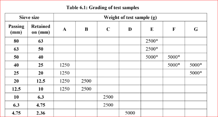
Rotate the machine at a speed of 30 – 33 revolutions per minute. The number of revolutions is 500 for grading A, B, C & D and 1000 for grading E, F & G. The machine should be

5 kg of sample for grading A, B, C & D and 10 kg for grading E, F & G

THE CALCULATION PART:

Original weight of aggregate sample = W1 g
Weight of aggregate sample retained = W2 g
Weight passing 1.7mm IS sieve = W1 - W2 g
Los Angeles Abrasion Value = (W1 - W2) / W1 X 100


Los angeles abrasion value should lies in below given range for different types of roads

Types of pavement layers                                         Max. Permissible Abrasion Value in %

1:WBM , SUB BASE COURSE                                                      60%

2:WBM BASE COURSE WITH BITUMEN SURFACE               50%

3: BITUMEN BOUND MACADAM                                             50%

4:WBM SURFACING COURSE                                                    40%

5: BITUMINOUS PENETRATION MACADAM                              40%

6:BITUMINOUS SURFACING DRESSING CEMENT
 CONCRETE SURFACING COURSE                                              35%

7:BITUMINOUS CONCRETE SURFACING COURSE                   30%

Monday 15 August 2016

Friday 12 August 2016

Highway Design-Parking Along Highways and Arterial Streets

Highway Parking Design
These paragraphs below deal with parking as it pertains to the mainlanes of a controlled access highway, the frontage roads for such a facility, and parking along urban and suburban arterials. Rest areas as parking facilities are not considered in this article.

Emergency Parking

Parking on and adjacent to the mainlanes of a highway will not be permitted except for emergency situations. It is of paramount importance, however, that provision be made for emergency parking. Shoulders of adequate design provide for this required parking space.

Curb Parking

In general, curb parking on urban/suburban arterial streets and frontage roads
should be discouraged. Where speed is low and the traffic volumes are well below capacity, curb parking may be permitted. However, at higher speeds and during periods of heavy traffic movement, curb parking is incompatible with arterial street service and desirably should not be permitted. Curb parking reduces capacity and interferes with free flow of adjacent traffic.
Elimination of curb parking can increase the capacity of four-to-six lane arterials by 50 to 60 percent. If curb parking is used on urban/suburban arterials or frontage roads under the conditions stated above, the following design requirements should be met:
  • provide parking lanes only at locations where needed
  • parallel parking preferred
  • confine parking lanes to outer side of street or frontage road
  • require that parking lane widths be 10 feet [3.0 meters]
  • restrict parking a minimum of 20 feet [6 meters] back from the radius of the intersection to allow for sight distance, turning clearance and, if desired, a short right turn lane.

Thursday 11 August 2016

Difference between Bridge and Flyover

The difference between Bridge and Flyover is based on the purpose of its usage and the location where it is built.

Bridges
  • Bridges are built to connect two points separated by a naturally occurring region like valley, river, sea or any other water bodies, etc.
  • They are usually lengthy depending upon the width of the valley or river.
  • Construction over river is tedious since foundation has to be carried out on the river bed.
  • Bridges are usually built for trains, buses and cars.

Flyovers
  • It is a structure which joints two or more points which are separated by an accessible route/s or a man made structure to cut the traffic for faster mode of travelling.
  • They are usually made over road junctions, roads, streets, etc.
  • The name itself suggests that you are flying over a traffic zone.
  • They are usually built for road vehicles.

Friday 19 February 2016

BAR BENDING SCHEDULE IMP


You may also like this topic of Estimation: 

How to calculate Quantity of Cement :Sand: Aggregate


If you are searching some important interview questions about cement than this article will boost your  knowledge today. 


                       Cement : The backbone of construction


Civil Engineering Competitive Exams Books :
For GATE Aspirants :
1: http://amzn.to/2A4iy9K
2: http://amzn.to/2hqwfrR ( more preferably)For SSC JE Aspirants :
1: http://amzn.to/2hqwfrR
2: http://amzn.to/2z7CGtm ( Highest rated book for SSC JE)
3: http://amzn.to/2iOjtqm


Wednesday 1 July 2015

Characteristic strength of concrete

Characteristic strength of concrete is one of the important properties of concrete which indeed unanimously by design engineeror any other person involved in the construction sector.
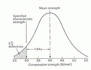
The compressive strength of concrete is given in terms of the characteristic compressive strength of 150 mm size cubes tested at 28 days (fck)- as per Indian Standards (ACI standards use cylinder of diameter 150 mm and height 300 mm). The characteristic strength is defined as the strength of the concrete below which not more than 5% of the test results are expected to fall.
This concept assumes a normal distribution of the strengths of the samples of concrete.
                               Normal Distribution curve on test specimens for determining compressive strength

Normal Distribution curve on test specimens for      determining compressive strength
The above sketch shows an idealized distribution of the values of compressive strength for a certain number of test specimens. The horizontal axis represents the values of compressive strength in MPa. The vertical axis represents the number of test samples for a
particular compressive strength. This is also termed as frequency.

The average of the values of compressive strength (mean strength) from the graph is 40 MPa. The characteristic strength (fck) is the value in the x-axis below which 5% of the total area under the curve falls. From the graph we can clearly say that 30 MPa is the characteristic strength of the given concrete mix. The value of fck is lower than fcm (40 MPa- mean strength) by 1.64σ, where σ is the standard deviation of the normal distribution.
So we can say the given concrete mix has a characteristic strength of 30 MPa or it is a M30 grade mix.
   M- Mix
* Note: For a 95% confidence level k=1.64 , hence k value varies on the confidence level of the experiment
Definition:
Characteristic strength of concrete is the strength of concrete specimens casted and tested as per given code of practice and cured for a period of 28 days; 95% of tested cubes should not have a value less than this value.

About piles

End Bearing Piles ::-

1:-In end bearing piles, the bottom end of the pile rests on a layer of especially strong soil or rock.
2:- The load of the building is transferred through the pile onto the strong layer.
3:-In a sense, this pile acts like a column.
4:-The key principle is that the bottom end rests on the surface which is the intersection of a weak and strong layer. The load therefore bypasses the weak layer and is safely transferred to the strong layer.


Friction Piles ::-

1:-Friction piles work on a different principle.
2:- The pile transfers the load of the building to the soil across the full height of the pile, by friction.
3:-In other words, the entire surface of the pile, which is cylindrical in shape, works to transfer the forces to the soil.


NOTE: In practice, however, each pile resists load by a combination of end bearing and friction

Thursday 23 October 2014

BURJ KHALIFA : THE NAME TELLS EVERYTHING== >>


10 Tallest Bridges In The World== >

1. Millau Viaduct, France – 343 metres (1,125 ft) tall. Opened in 2004, this 4 lanesbridge is a cable-stayed bridge that spans the valley of the River Tarn near Millau in southern France. The bridge has 7 piers of different heights. The second one is the tallest with a height of 244.96 m (803 ft 8 in) – making it the tallest structure in France, taller than the Eiffel Tower!
Tallest Bridges In The World: Millau Viaduct, France


2. Russky Bridge, Russia – 320.9 metres (1,053 ft) tall. Located in Vladivostok, the bridge was completed in 2012. It connects the mainland part of the city with Russky Island
Tallest Bridges In The World: Russky Bridge, Russia


3. Sutong Bridge, China – 306 metres (1,004 ft) tall. Opened in 2008, this bridge spans the Yangtze River between Nantong and Changshu
Tallest Bridges In The World: Sutong Bridge, China


4. Akashi-Kaikyo Bridge, Japan – 298.3 metres (979 ft) tall. This beautiful suspension bridge was opened in 1998. It links the city of Kobe on the mainland of Honshu to Iwaya on Awaji Island. It is the tallest suspension bridge in the world
Tallest Bridges In The World: Akashi-Kaikyo Bridge, Japan


5. Stonecutters Bridge, Hong Kong – 298 metres (978 ft) tall. A high level cable-stayed bridge which spans the Rambler Channel in Hong Kong, connecting Nam Wan Kok, Tsing Yi island and Stonecutters Island. The bridge deck was completed and opened to the public in 2009
Tallest Bridges In The World: Stonecutters Bridge, Hong Kong


6. Yi Sun-sin Bridge, South Korea – 270 metres (890 ft) tall. Except of being the 6th tallest bridge in the world, it’s also the second tallest suspension bridge in the world and the fourth longest suspension bridge in the world
Tallest Bridges In The World: Yi Sun-sin Bridge, South Korea


7. Jingyue Bridge, China – 265 metres (869 ft) tall. This cable-stayed bridge in Jianli County was opened in 2010 and crosses the Yangtze River
Tallest Bridges In The World: Jingyue Bridge, China


8. Great Belt East Bridge, Denmark – 254 metres (833 ft) tall. Opened in 1998, this bridgeruns between the Danish islands of Zealand and Funen. It is the third tallest bridge in Europe
Tallest Bridges In The World: Great Belt East Bridge, Denmark


9. Zhongxian Huyu Expressway Bridge, China – 247.5 metres (812 ft) tall. Completed in 2010, this bridge crosses the Yangtze River in Zhong County
Tallest Bridges In The World: Zhongxian Huyu Expressway Bridge, China


10. Jiujiang Fuyin Expressway Bridge, China – 244.3 metres (802 ft) tall. A Cable-stayed bridge under construction and should be completed by the end of 2013. With a main span of 818 m (2,684 ft) it will become one of the longest cable-stayed bridges in the world upon its completion
Tallest Bridges In The World: Jiujiang Fuyin Expressway Bridge, China

Friday 18 October 2013

Overview of arches

Overview of arches

JOIN US ==>> ON FACEBOOK


the ancient Romans were masters at arch constructionArches
An arch is an opening spanned by a collection of wedge shaped pieces (voussoirs) which stay in position by pressing in on one another. The joints between the pieces appear to radiate from some central point lying within the opening, and sometimes from points which lie outside, so every type of arch has a characteristic curvature. The simplest and visually most natural shape for an arch is the semicircle but many other designs have been used.
the principal parts of a conventional semicircular archHow an Arch "Works"
The central voussoir (keystone) is traditionally the last to be set into position to "lock" the whole thing into a strong and stable structure. A keystone is not always necessary, however; there may be a joint at the apex instead, as is common in Gothic arches. Gravity tries to pull the keystone downwards, but the thrust is carried on either side by the voussoirs immediately flanking it. These in turn have their total thrust carried through the whole semicircle of pieces in a sideways direction until it reaches the vertical part of the wall and can descend directly to the foundation. In short, an arch works because vertical weight is deflected into sideways thrust and transferred to the walls.
The graphic at right shows the principal parts of a conventional semicircular arch. Most arches of this type are made slightly taller than true semicircles -- thespring line is above the impost line -- simply because it looks "normal." The smaller inset drawing shows how an arch converts the downward pressing weight of the wall above it into outward thrust.
Limitations of the Arch
Because of the sideways thrust the arch is not a stable structure in itself, because that thrust tries to make the bottom of of the structure spread out on either side. To stop this happening there must be enough solid material at the side to act as flanking buttresses. For this reason an arch is more naturally placed within the body of a wall rather than at either end. Series of arches are suitable for bridge building or aqueducts because the river banks or valley sides make excellent buttresses. Similarly, long colonnades consisting of repeated arches, such as the ancient Roman aqueducts, need sizeable lengths of unperforated wall at each end to beat the combined thrust of the entire series, though intervening posts or piers can themselves be quite slender.
Solid flanks are unnecessary where colonnades are completely circular, for their entire weight becomes a single, unified downward thrust. The best example of such a construction is the Colosseum at Rome, consisting of three stories of circular arch colonnades surmounted by a visually solid fourth-story wall. The inherent stability of the arch is also testified to by the Colosseum; built between 70 and 82 A.D., the structure is still standing and is still structurally sound.

the post and lintel and corbelled are not true arches
four types of arches


four types of arches

Monday 22 April 2013

TYPES OF BRIDGES :


How do bridge's work????


Although there are many types of bridges most bridges work by balancing compression and tension. Place a flexible object like an eraser, sponge, or small piece of bread between your thumb and index finger. Press your fingers together. One side of the object will bend inwards and shorten while the other will bend outwards and lengthen. The shorter side has been compressed, while the other side is under tension. Bridge
components experience these tension and compression stresses


ARCH BRIDGE ==>>
Arch bridge are structures in which each span forms an arch. The arch bridge is one of the oldest types of bridges. Early arch bridges were made from stone. The spans range up to about 1700 ft.


GIRDER BRIDGES ==>>

Girder bridges are made of beams called girders. The ends of the beams or girders rest on piers or abutments. The span length of girder bridges ranges up to about 1000 ft.

TRUSS BRIDGE==>>

Truss bridges are supported by frameworks called trusses. Trusses are beams arranged to form triangles.

CANTILEVER BRIDGE==>>

Cantilever bridges consist of two independent beams, cantilevers, that extend from opposite banks of a waterway. Cantilever bridges have spans as long at 1800 ft.

CABLE STAYED BRIDGE==>>

Cable-stayed bridges have roadways that hang from cables. The cables are connected directly to towers.

MOVEABLE BRIDGE==>>

Moveable bridges have roadway that is moved to provide enough clearance for boats or large ships to pass. An example of a moveable bridge is a drawbridge that tilts the roadway upward.

SUSPENSION BRIDGES==>>

Suspension bridges may be the most impressive type of bridge with their long main span and beauty. These bridges have a roadway that hangs from steel cables supported by two high towers. The difference between suspension bridges and cable-stayed bridges is that suspension bridge cables are not directly connected to the towers. The cables of a suspension bridge are not connected to the bridge - the cables pass through a hole in the top of the towers.


A suspension bridge has at least two main cables. These cables extend from one end of the bridge to the other. Suspender cables hang from these main cables. The other end of the suspender attaches to the roadway.


Suspension bridges have the longest spans in the world and are used to cross great distances. These types of bridges are used to cross deep water channels, cannons or gorges, where construction of supporting piers can be difficult. The towers can be placed far apart eliminating the need for multiple towers and piers. Some suspension bridges have a main span longer then 4000 ft. The longest suspension bridge in the world is in Japan (the Akashi- Kaikyo Bridge) and has a span over a mile long. The largest bridges have cables several feet wide which weigh thousands of pounds per foot. For that reason the cables are spun in place.

Monday 8 April 2013

==>> MOMENT DISTRIBUTION METHOD'S THEORY IN VERY SIMPLE WAY<<==

                                       ==>> MOMENT DISTRIBUTION METHOD
                                                                         OR
                                                    [HARDY -CROSS METHOD]
                                                                         OR
                                      METHOD OF SUCCESSIVE APPROXIMATION<<==

==>>   It is based on stiffness approach and stiffness is defined as the moment required to produce unit rotation....

FIRST we have to clear all terms which we are going to learn in this method

K=STIFFNESS,
I=MOMENT OF INERTIA,
E=MODULUS OF ELASTICITY
L=LENGTH OF WHOLE SPAN

In this method some formulas are given bellow ==>>

1==>> If the far end is fixed then stiffness is ==>> K= 4EI/L

2==>>If the far end is hinged then stiffness is ==>> K=3EI/L

3==>>If the far end is free then stiffness is ==>> K=0

Here is the example==>>


Fixed far end are==>> OB and OD
Free far end are==>> OF
Hinged far end are==>> OC and OE

Length of each span  OB=L1 ,,, OD=L2 ,,, OF =L3 ,,, OC=L4 ,,, OE=L5

Now we have to calculate individual and total stiffness==>>
Stiffness of OB IS ==>> K1=4EI / L1 [FAR END B IS FIXED]
Stiffness of OD is ==>> K2=4EI / L2  [FAR END D IS FIXED]
Stiffness of OF is ==>> K3=K=0    [FAR END F IS FREE]
Stiffness of OC is ==>> K4=3EI / L4  [FAR END C IS HINGED]
Stiffness of OE is ==>>  K5=3EI / L5  [FAR END E IS HINGED]

Now we have to calculate TOTAL STIFFNESS ,so
TOTAL STIFFNESS ==>>K=K1+K2+K3+K4+K5
K=4EI / L1+4EI / L2+0+3EI / L4+3EI / L5

After this steps we have to calculate RELATIVE STIFFNESS ==>>

RELATIVE STIFFNESS is defined as the individual stiffness/total stiffness

==>>RELATIVE STIFFNESS of all members are==>>

For OB=K1 / K;
For OD=K2 / K;
For OF=K3 / K;
For OC=K4 / K;
For OE=K5 / K;

Some other terms used in MOMENT DISTRIBUTION METHOD are==>>

CARRY OVER MOMENT==>>
If moment M is applied at a joint B then carry over moment is the moment which is develop at the far end..

==>> If any beam fixed at one end and supported at other end ...then moment develop at the fixed end is half of the moment develop at the supported end...

A==>>FIXED END , B==>> SUPPORTED END...
MOMENT AT B= M
Then MOMENT develop in A is = M / 2;

CARRY OVER FACTOR==>> is given by

CARRY OVER MOMENT /  APPLIED MOMENT

MOMENT ABOUT A / MOMENT ABOUT B


Thursday 13 December 2012

SWAY AND NON-SWAY OF STRUCTURE:

SWAY AND NON-SWAY OF STRUCTURE:

NON-SWAY==>> If structure in stable in any condition then it is non sway condition of structure...

CONDITION FOR NON-SWAY=>

For non - sway structure have same moment of inertia through all members ...loads applied is centric for all members (it may be UDL or may be point load)... Supports are at same level..


                                                                              [1ST]                                  [2ND]

1ST structure ==>> NON-SWAY

2ND structure ==>> SWAY


SWAY==>> If structure is not in stable position ..and structure tilled , then it is called sway of structure..

CONDITION FOR SWAY==>>

=> IF moment of inertia of all members are different then sway come into action ...structure tilled in that side where moment of inertia is less...

=> IF applied load is not in center than sway also come in action.. at which side load is less at that side sway will come..

=>IF supports of structure are not in same level than sway also come in structure...

=>IF all condition are applying in single structure than we consider all condition at same time...


Best ever book for Structure: 

Theory of structures by s. ramamrutham: Buy it From Amazon Directly


Wow , after reading about sway and non sway 

you are curious about knowing Bar Bending Schedule, how to calculate those steel , which we use in construction , which are used before occurring of sway and non sway , so here are the article for you 

How to calculate Quantity of steel


If you are searching some important interview questions about cement than this article will boost your  knowledge today. 

Cement : The backbone of construction


Civil Engineering Competitive Exams Books :For GATE Aspirants :1: http://amzn.to/2A4iy9K 2: http://amzn.to/2hqwfrR ( more preferably)For SSC JE Aspirants :
1: http://amzn.to/2hqwfrR
2: http://amzn.to/2z7CGtm ( Highest rated book for SSC JE)
3: http://amzn.to/2iOjtqm

Get Posts In Your Inbox