Showing posts with label BUILDING CONSTRUCTION. Show all posts

Sunday 17 August 2014

LOS ANGELES ABRASION TEST , HOW and WHY TO PERFORM

LOS ANGELES ABRASION TEST:


This is hardness test for aggregates, used in Laboratory  to determine the hardness value or abrasion value 
APPARATUS :

 Los Angeles Abrasion Testing Machine ,
Abrasive Charge – Cast iron or steel balls ,
Test sieve – 1.70 mm IS sieve ,
 Balance of capacity 10 kg , Oven , Tray

The aggregate used in surface course of the highway pavements are subjected to wearing due to movement of traffic. 

When vehicles move on the road, the soil particles present between the pneumatic tyres and road surface cause abrasion of road aggregates. 

The steel reamed wheels of animal driven vehicles also cause considerable abrasion of the road surface. 

Therefore, the road aggregates should be hard enough to resist abrasion. 

The principle of Los Angeles abrasion test is to produce abrasive action by use of standard steel balls which when mixed with aggregates and rotated in a drum for specific number of revolutions also causes impact on aggregates. 

The percentage wear of the aggregates due to rubbing with steel balls is determined and is known as Los Angeles Abrasion Value.


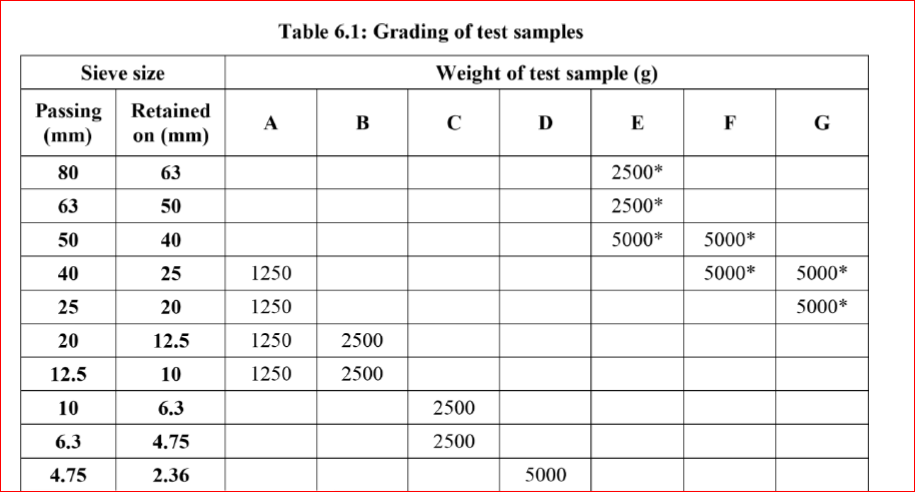
Key point of los angles test:

Rotate the machine at a speed of 30 – 33 revolutions per minute. The number of revolutions is 500 for grading A, B, C & D and 1000 for grading E, F & G. The machine should be

5 kg of sample for grading A, B, C & D and 10 kg for grading E, F & G

THE CALCULATION PART:

Original weight of aggregate sample = W1 g
Weight of aggregate sample retained = W2 g
Weight passing 1.7mm IS sieve = W1 - W2 g
Los Angeles Abrasion Value = (W1 - W2) / W1 X 100


Los angeles abrasion value should lies in below given range for different types of roads


Types of pavement layers                                         Max. Permissible Abrasion Value in %

1:WBM , SUB BASE COURSE                                                      60%

2:WBM BASE COURSE WITH BITUMEN SURFACE               50%

3: BITUMEN BOUND MACADAM                                             50%

4:WBM SURFACING COURSE                                                    40%

5: BITUMINOUS PENETRATION MACADAM                              40%

6:BITUMINOUS SURFACING DRESSING CEMENT
 CONCRETE SURFACING COURSE                                              35%

7:BITUMINOUS CONCRETE SURFACING COURSE                   30%

Monday 28 October 2013

Test for Bricks:


(1) Absorption:
A brick is taken and it is weighed dry. It is then immersed in water for a period of 16 hours. It is weighed again and the difference in weight indicates the amount of water absorbed by the brick. It should not in exceed 20 per cent of weight of dry brick.
(2) Compressive/Crushing strength of Bricks:
The crushing strength of a brick is found out by placing it in a compression testing machine. It is pressed till it breaks.  the minimum crushing or compressive strength of bricks is 3.50 N/mm2. 

The bricks with crushing strength in between of 7 N/mm2 to 14 N/mm2 are graded as A and those having above 14 N/mm2 are graded as AA, 
(3) Hardness test on bricks:
In this test, a scratch is made on brick surface with the help of a finger nail. If no impression is left on the surface, the brick is r sufficiently hard.
(4) Presence of soluble salts:
The soluble salts, if present in cause efflorescence on the surface of bricks. For finding out the presence of soluble salts in a brick, it is immersed in water for 24 hours. It is then taken out and allowed to dry in shade. The absence of grey or white deposits on indicates absence of soluble salts.

If the white deposits cover about 10 per cent surface, the efflorescence is said to be slight and it is considered as moderate, when the white deposits cover about 50 per cent of surface. If grey or white deposits are found on more than 50 per cent of surface, the efflorescence becomes heavy and it is treated as serious, when such deposits are converted into powdery mass.
(5) Shape and size:
In this test, a brick is closely inspected. It should be of standard size and its shape should be truly rectangular with sharp edges. For this purpose, 20 bricks of standard size (190 mm x 90 mm x 90 mm) are selected at random and they are stacked lengthwise, along the width and along the height.
(6) Soundness test on brick:
In this test, the two bricks are taken and they are struck with each other. 
The bricks should not break and a clear ringing sound should be produced.

Other test can be perform but these 6 are the important once.

Monday 15 April 2013

==>>DEEP FOUNDATION==>>

DEEP FOUNDATION==>>
Deep foundation are those in which the depth of the foundation is very large i comparison to its width.. Deep foundation are not constructed by ordinary methods of open pit excavations.

TYPE OF DEEP FOUNDATION==>>

1==> PILE FOUNDATION
2==> PIER FOUNDATION
3==> CAISSON FOUNDATION


PILE FOUNDATION==>> Pile foundation is that type of foundation in which the loads are taken to a low level by means of vertical members which may be of timber , concrete or steel...

PIER FOUNDATION==>> A pier foundation consists of a cylindrical column of large diameter to support and transfer large super imposed loads to the firm strata below..
The difference between pile foundation and pier foundation lies in the method of construction.Though pile foundation transfer the load through friction or bearing , pier foundation transfer the loads only through bearing.

CAISSON FOUNDATION==>> Well foundation or caissons are box like structure circular or rectangular which are sunk from the surface of either land or water to the desired depth.
They are much larger diameter than pier foundations.
Use of well foundation
=> Wharves , quay walls , docks.
=> Bridge piers and abutments in rivers, lakes etc.
=>Large water front structures such as pump houses , subjected to heavy vertical and horizontal loads.

==>> Well foundation are hollow from inside , which may filled with sand , ans are plugged at the bottom. The load is transferred through the perimeter wall, called steining.
This foundation are not use for buildings construction...

TYPES OF SHALLOW FOUNDATION==>>

Sunday 14 April 2013

==>> CLASSIFICATION OF BRICKS==>>


==>> CLASSIFICATION OF BRICKS==>>

FIRST CLASS BRICKS==>>

1. These are thoroughly burnt and are of deep red, cherry or copper colour.
2. The surface should be smooth and rectangular, with parallel, sharp and straight edges
and square corners.
3. These should be free from flaws, cracks and stones.
4. These should have uniform texture.
5. No impression should be left on the brick when a scratch is made by a finger nail.
6. The fractured surface of the brick should not show lumps of lime.
7. A metallic or ringing sound should come when two bricks are struck against each other.
8. Water absorption should be 12–15% of its dry weight when immersed in cold water for
24 hours.
9. The crushing strength of the brick should not be less than 10 N/mm2. This limit varies
with different Government organizations around the country.
Uses: First class bricks are recommended for pointing, exposed face work in masonry
structures, flooring and reinforced brick work.

SECOND CLASS BRICKS==>>


  Are supposed to have the same requirements as the first class ones except that

1. Small cracks and distortions are permitted.
2. A little higher water absorption of about 16–20% of its dry weight is allowed.
3. The crushing strength should not be less than 7.0 N/mm2.
Uses: Second class bricks are recommended for all important or unimportant hidden masonry
works and centering of reinforced brick and reinforced cement concrete (RCC) structures.


THIRD CLASS BRICKS==>>

Are underburnt. They are soft and light-coloured producing a dull sound when struck against
each other. Water absorption is about 25 per cent of dry weight.

Uses : It is used for building temporary structures.

FORTH CLASS BRICKS==>>
Are overburnt and badly distorted in shape and size and are brittle in
nature.

Uses: The ballast of such bricks is used for foundation and floors in lime concrete and road
metal.

==>>

Friday 12 April 2013

==>> SUB SOIL EXPLORATION<<==

==>> The purposes of subsoil exploration include the following:


l. Determining the nature of soil at the site and its stratification
2. Obtaining disturbed and undisturbed soil samples for visual identification and
appropriate laboratory tests
3. Determining the depth and nature of bedrock, if and when encountered
4. Performing somc in sl/u lield tests, such as permeability tests. vane
shear tests , and standard penetration tests
5. Observing drainage conditions from and into thc site
6. Assessinga ny special construction problems with respect to the existing  structure  nearby
7. Determining the position of the water table

Thursday 7 February 2013

==>>3D TOOLS USED IN AUTO CAD==>>


==>>3D TOOLS USED IN AUTO CAD==>>

FOR 2D TOOLS CLICK ON THIS LINK==>>

2D TOOLS USED IN CIVIL ENGINEERING

3darray – Creates an array of 3D models in 3D space
3dface (3f) – Creates a 3- or 4-sided 3D mesh behind which other features
can be hidden
3dmesh – Creates a 3D mesh in 3D space
3dcorbit – Allows methods of manipulating 3D models on screen
3ddistance – Allows the controlling of the distance of 3D models from the operator
3dfl y – Allows walkthroughs in any 3D plane
3dforbit – Controls the viewing of 3D models without constraint
3dmove – Shows a 3D move gizmo. Moves 3D objects
3dorbit (3do) – Allows a continuous movement and other methods of
manipulation of 3D models on screen
3dorbitctr – Allows further and a variety of other methods of
manipulation of 3D models on screen

3dpan – Allows the panning of 3D models vertically and horizontally on screen
3drotate – Displays a 3D rotate gizmo. Rotates 3D objects
3dscale – Shows a 3D scale gizmo. Scales 3D objects
3dsin – Brings the 3D Studio File Import dialog on screen
3dsout – Brings the 3D Studio Output File dialog on screen
3ddwf – Brings up the Export 3D DWF dialog on screen
3dwalk – Starts walk mode in 3D
anipath – Opens the Motion Path Animation dialog
Align – Allows selected entities to be aligned to selected points in 3D space
Ameconvert – Converts AME solid models (from Release 12) into
AutoCAD 2000 solid models
Box – Creates a 3D solid box

Cone – Creates a 3D model of a cone
convertoldlights – Converts lighting from previous releases to AutoCAD
2010 lighting
convertoldmaterials – Converts materials from previous releases to
AutoCAD 2010 materials
convtosolid – Converts plines and circles with thickness to 3D solids
convtosurface – Converts objects to surfaces
Cylinder – Creates a 3D cylinder
Dducs (uc) – Brings the UCS dialog on screen
Edgesurf – Creates a 3D mesh surface from four adjoining edges
Extrude (ext) – Extrudes a closed polyline
Flatshot – Brings the Flatshot dialog to screen
Freepoint – Point light created without settings
Freespot – Spot light created without settings
Helix – Constructs a helix
Interfere – Creates an interference solid from a selection of several solids
Intersect (in) – Creates an intersection solid from a group of solids
Light – Enables different forms of lighting to be placed in a scene
Lightlist – Opens the Lights in Model palette
Loft – Activates the Loft command

Materials – Opens the Materials palette
Matlib – Outdated instruction
Mesh – Can be used to set tessellations for a 3D primitive
Meshrefi ne – Refi nes the meshing of a 3D object
Meshsmooth – Increases the smoothness of 3D objects
Meshsmooth – Smoothes outlines of 3D objects
Mirror3d – Mirrors 3D models in 3D space in selected directions
Mview (mv) – When in PSpace brings in MSpace objects
Pface – Allows the construction of a 3D mesh through a number of
selected vertices
Plan – Allows a drawing in 3D space to be seen in plan (UCS World)
Planesurf – Creates a planar surface
Pointlight – Allows a point light to be created

Pspace (ps) – Changes MSpace to PSpace
Pyramid – Creates a pyramid
-render – Can be used to make rendering settings from the command line.
Note the hyphen ( - ) must precede render
Renderpresets – Opens the Render Presets Manager dialog
Renderwin – Opens the Render window
Revolve (rev) – Forms a solid of revolution from outlines
Revsurf – Creates a solid of revolution from a pline
Rmat – Brings the Materials palette on screen
Rpref (rpr) – Opens the Advanced Render Settings palette

Section (sec) – Creates a section plane in a 3D model
Shade (sha) – Shades a selected 3D model
Slice (sl) – Allows a 3D model to be cut into several parts
Solprof – Creates a profi le from a 3D solid model drawing
Sphere – Creates a 3D solid model sphere
Spotlight – Creates a spotlight
Stlout – Saves a 3D model drawing in ASCII or binary format
Sunproperties – Opens the Sun Properties palette
Sweep – Creates a 3D model from a 2D outline along a path

Tabsurf – Creates a 3D solid from an outline and a direction vector
Torus (tor) – Allows a 3D torus to be created
Ucs – Allows settings of the UCS plane
Union (uni) – Unites 3D solids into a single solid
View – Creates view settings for 3D models
Visualstyles – Opens the Visual Styles Manager palette
Vpoint – Allows viewing positions to be set from x,y,z entries
Vports – Brings the Viewports dialog on screen
Wedge (we) – Creates a 3D solid in the shape of a wedge
Xedges – Creates a 3D wireframe for a 3D solid


INTERNAL TOOLS==>>

Etransmit – Brings the Create Transmittal
Publish – Brings the Publish dialog to screen

==>> USE OF AUTO CAD IN CIVIL ENGINEERING==>>


AUTO CAD==>>  Automatic Computer Aided Design
It is useful for building construction to draw 3D view of buildings parts in computer...

AutoCAD 2010 allows the use of over 300 tools. Some operators prefer using the word “ commands ” , although command as an alternative to tool is not in common use today. The abbreviations for tools which can be abbreviated are included in brackets after the tool name. Tool names can be entered in upper or lower case.
2D and 3D both work can be done in AUTOCAD

2D TOOLS USED IN AUTO CAD==>>

FOR 3D TOOLS CLICK ON THIS LINK==>>

3D TOOLS USED IN AUTO CAD


About – Brings the About AutoCAD bitmap on screen
Appload – Brings the Load/Unload Applications dialog to screen
Adcenter (dc) – Brings the DesignCenter palette on screen
Align (al) – Aligns objects between chosen points
Arc (a) – Creates an arc
Area – States in square units the area selected from a number of points
Array (ar) – Creates Rectangular or Polar arrays in 2D
Ase – Brings the dbConnect Manager on screen
Attdef – Brings the Attribute Defi nition dialog on screen
Attedit – Allows editing of attributes from the Command line
Audit – Checks and fi xes any errors in a drawing
Autopublish – Creates a DWF fi le for the drawing on screen
Bhatch (h) – Brings the Boundary Hatch dialog on screen
Block – Brings the Block Defi nition dialog on screen
Bmake (b) – Brings the Block Defi nition dialog on screen
Bmpout – Brings the Create Raster File dialog on screen
Boundary (bo) – Brings the Boundary Creation dialog on screen
Break (br) – Breaks an object into parts
Cal – Calculates mathematical expressions
Chamfer (cha) – Creates a chamfer between two entities
Chprop (ch) – Brings the Properties window on screen
Circle (c) – Creates a circle
Copytolayer – Copies objects from one layer to another

Copy (co) – Creates a single or multiple copies of selected entities
Copyclip (Ctrl C) – Copies a drawing or part of a drawing for inserting
into a document from another application
Copylink – Forms a link between an AutoCAD drawing and its
appearance in another application such as a word-processing package
Customize – Brings the Customize dialog to screen, allowing the
customisation of toolbars, palettes etc.
Dashboard – Has the same action as Ribbon
Dashboardclose – Closes the Ribbon
Ddattdef (at) – Brings the Attribute Defi nition dialog to screen
Ddatte (ate) – Edits individual attribute values
Ddcolor (col) – Brings the Select Color dialog on screen
Ddedit (ed) – The Text Formatting dialog box appears on selecting text
Ddim (d) – Brings the Dimension Style Manager dialog box on screen
Ddinsert (i) – Brings the Insert dialog on screen
Ddmodify – Brings the Properties window on screen
Ddosnap (os) – Brings the Drafting Settings dialog on screen
Ddptype – Brings the Point Style dialog on screen
Ddrmodes (rm) – Brings the Drafting Settings dialog on screen
Ddunits (un) – Brings the Drawing Units dialog on screen
Ddview (v) – Brings the View Manager on screen
Del – Allows a fi le to be deleted
Dgnexport – Creates a MicroStation V8 dgn fi le from the drawing on
screen
Dgnimport – Allows a MicroStation V8 dgn fi le to be imported as an
AutoCAD dwg fi le

Dim – Starts a session of dimensioning
Dimension tools – The Dimension toolbar contains the following tools –
Linear , Aligned , Arc Length , Ordinate , Radius , Jogged , Diameter ,
Angular , Quick Dimension , Baseline , Continue , Quick Leader ,
Tolerance , Center Mark , Dimension Edit , Dimension Edit Text ,
Update and Dimension Style
Dim1 – Allows the addition of a single dimension to a drawing
Dist (di) – Measures the distance between two points in coordinate units
Distantlight – Creates a distant light
Divide (div) – Divides an entity into equal parts
Donut (do) – Creates a donut
Dsviewer – Brings the Aerial View window on screen
Dtext (dt) – Creates dynamic text. Text appears in drawing area as it is
entered
Dxbin – Brings the Select DXB File dialog on screen
Dxfi n – Brings the Select File dialog on screen
Dxfout – Brings the Save Drawing As dialog on screen

Ellipse (el) – Creates an ellipse
Erase (e) – Erases selected entities from a drawing
Exit – Ends a drawing session and closes AutoCAD 2010
Explode (x) – Explodes a block or group into its various entities
Explorer – Brings Windows Explorer on screen
Export (exp) – Brings the Export Data dialog on screen
Extend (ex) – To extend an entity to another
Fillet (f) – Creates a fi llet between two entities
Filter – Brings the Object Selection Filters dialog on screen
Gradient – Brings the Hatch and Gradient dialog on screen

Group (g) – Brings the Object Grouping dialog on screen
Hatch – Allows hatching by the entry responses to prompts
Hatchedit (he) – Allows editing of associative hatching
Help – Brings the AutoCAD 2010 Help: User Documentation dialog on
screen
Hide (hi) – Hides parts behind 3D meshes in 3D models
Id – Identifi es a point on screen in coordinate units
Imageadjust (iad) – Allows adjustment of images
Imageattach (iat) – Brings the Select Image File dialog on screen
Imageclip – Allows clipping of images
Import – Brings the Import File dialog on screen
Insert (i) – Brings the Insert dialog on screen
Insertobj – Brings the Insert Object dialog on screen
Isoplane (Ctrl E) – Sets the isoplane when constructing an isometric
drawing

Join (j) – Joins lines which are in line with each other or arcs which are
from the same centre point
Laycur – Changes layer of selected objects to current layer
Layer (la) – Brings the Layer Properties Manager dialog on screen
Layout – Allows editing of layouts
Lengthen (len) – Lengthens an entity on screen
Limits – Sets the drawing limits in coordinate units
Line (l) – Creates a line
Linetype (lt) – Brings the Linetype Manager dialog on screen
List (li) – Lists in a text window details of any entity or group of entities
selected

Load – Brings the Select Shape File dialog on screen
Ltscale (lts) – Allows the linetype scale to be adjusted
Measure (me) – Allows measured intervals to be placed along entities
Menu – Brings the Select Customization File dialog on screen
Menuload – Brings the Load/Unload Customizations dialog on screen
Mirror (mi) – Creates an identical mirror image of selected entities
Mledit – Brings the Multiline Edit Tools dialog on screen


Mline (ml) – Creates mlines
Mlstyle – Brings the Multiline Styles dialog on screen
Move (m) – Allows selected entities to be moved
Mslide – Brings the Create Slide File dialog on screen
Mspace (ms) – When in PSpace changes to MSpace
Mtext (mt or t) – Brings the Multiline Text Editor on screen
Mview (mv) – To make settings of viewports in Paper Space
Mvsetup – Allows drawing specifi cations to be set up
New (Ctrl N) – Brings the Select template dialog on screen
Notepad – For editing fi les from Windows Notepad
Offset (o) – Offsets selected entity by a stated distance
Oops – Cancels the effect of using Erase
Open – Brings the Select File dialog on screen
Options – Brings the Options dialog to screen

Ortho – Allows ortho to be set ON/OFF
Osnap (os) – Brings the Drafting Settings dialog to screen
Pagesetup – Brings either the Page Setup Manager on screen
Pan (p) – Drags a drawing in any direction
Pbrush – Brings Windows Paint on screen
Pedit (pe) – Allows editing of polylines. One of the options is Multiple ,
allowing continuous editing of polylines without closing the command
Pline (pl) – Creates a polyline
Plot (Ctrl P) – Brings the Plot dialog to screen
Point (po) – Allows a point to be placed on screen
Polygon (pol) – Creates a polygon
Polyline (pl) – Creates a polyline
Preferences (pr) – Brings the Options dialog on screen
Preview (pre) – Brings the print/plot preview box on screen
Properties – Brings the Properties palette on screen
Psfi ll – Allows polylines to be fi lled with patterns
Psout – Brings the Create Postscript File dialog on screen
Purge (pu) – Purges unwanted data from a drawing before saving to fi le
Qsave – Saves the drawing fi le to its current name in AutoCAD 2010
Quickcalc (qc) – Brings the QUICKCALC palette to screen
Quit – Ends a drawing session and closes down AutoCAD 2010
Ray – A construction line from a point
Recover – Brings the Select File dialog on screen to allow recovery of
selected drawings as necessary
Recoverall – Repairs damaged drawing
Rectang (rec) – Creates a pline rectangle
Redefi ne – If an AutoCAD command name has been turned off by
Undefi ne , Redefi ne turns the command name back on
Redo – Cancels the last Undo

edrawall (ra) – Redraws the whole of a drawing
Regen (re) – Regenerates the contents of the AutoCAD 2010 drawing area

Regenall (rea) – Regenerates the whole of a drawing
Region (reg) – Creates a region from an area within a boundary
Rename (ren) – Brings the Rename dialog on screen
Revcloud – Forms a cloud-like outline around objects in a drawing to
which attention needs to be drawn
Ribbon – Brings the ribbon on screen
Ribbonclose – Closes the ribbon
Save (Ctrl S) – Brings the Save Drawing As dialog box on screen
Saveas – Brings the Save Drawing As dialog box on screen
Saveimg – Brings the Render Output File dialog on screen
Scale (sc) – Allows selected entities to be scaled in size – smaller or larger
Script (scr) – Brings the Select Script File dialog on screen
Setvar (set) – Can be used to bring a list of the settings of set variables
into an AutoCAD Text window
Shape – Inserts an already loaded shape into a drawing
Shell – Allows MS-DOS commands to be entered
Sketch – Allows freehand sketching
Solid (so) – Creates a fi lled outline in triangular parts
Spell (sp) – Brings the Check Spelling dialog on screen
Spline (spl) – Creates a spline curve through selected points
Splinedit (spe) – Allows the editing of a spline curve
Status – Shows the status (particularly memory use) in a Text window
Stretch (s) – Allows selected entities to be stretched
Style (st) – Brings the Text Styles dialog on screen
Tablet (ta) – Allows a tablet to be used with a pointing device
Tbconfi g – Brings the Customize User Interface dialog on screen to
allow configuration of a toolbar
Text – Allows text from the Command line to be entered into a drawing
Thickness (th) – Sets the thickness for the Elevation command
Tilemode – Allows settings to enable Paper Space
Tolerance – Brings the Geometric Tolerance dialog on screen
Toolbar (to) – Brings the Customize User Interface dialog on screen
Trim (tr) – Allows entities to be trimmed up to other entities
Type – Types the contents of a named fi le to screen
UCS – Allows selection of UCS (User Coordinate System) facilities
Undefi ne – Suppresses an AutoCAD command name
Undo (u) (Ctrl Z) – Undoes the last action of a tool

View – Brings the View dialog on screen
Vplayer – Controls the visibility of layers in Paper Space
Vports – Brings the Viewports dialog on screen
Vslide – Brings the Select Slide File dialog on screen
Wblock (w) – Brings the Create Drawing File dialog on screen
Wmfi n – Brings the Import WMF dialog on screen
Wipeout – Forms a polygonal outline within which all crossed parts of
objects are erased
Wmfopts – Brings the WMF in Options dialog on screen
Wmfout – Brings the Create WMF File dialog on screen
Xattach (xa) – Brings the Select Reference File dialog on screen
Xline – Creates a construction line
Xref (xr) – Brings the Xref Manager dialog on screen
Zoom (z) – Brings the zoom tool into action


Sunday 30 December 2012

==>>CAVITY WALLS==>>

CAVITY WALLS==>>

A cavity wall or hollow wall is the one which consists of two separate walls,called leaves or skins with a cavity or gap in between.
The two leaves of a cavity may be of equal thickness if it is a non - load bearing wall, or the internal leaf may be thicker than the external leaf, to meet the structural requirements.

Cavity walls are often constructed for giving better thermal insulation to the building...
it also prevents the dampness to enter ans acts as sound insulation . Thus they are normally the outer walls of the building.

SIZE OF CAVITY WALLS==>>

The size of cavity wall varies from 4 to 10 cm ...The inner and outer skins should not be less than 10 cm each (half brick)...

ADVANTAGES OF CAVITY WALLS==>>

=>> External moisture (dampness) cannot travel inside the building..

=>> Transmission of heat from external face to the inside the room is very much reduced..

=>> Cavity walls also offer good insulation against sound...

=>>The nuisance of efflorescence is also very much reduced..

=>> They are cheaper and economical..

=>> Loads on foundation are reduced because of lesser solid thickness...

Saturday 8 December 2012

==>>TYPES OF FOUNDATION==>>

TYPES OF FOUNDATION==>>

1=>> SHALLOW FOUNDATION
2=>> DEEP FOUNDATION

==>> SHALLOW FOUNDATION =>>Foundation is the shallow If depth is equal to or less than its width.
[dept<=width]

==>> DEEP FOUNDATION=>> Foundation is the deep If depth is equal to or greater than its width..
[depth=>width]

TYPES OF SHALLOW FOUNDATION==>>

1->SPREAD FOOTING
2->COMBINED FOOTING
3->STRAP FOOTING
4->MAT FOUNDATION OR RAFT FOUNDATION

SPREAD FOOTING==>> Spread footing are those which spread the super imposed load of wall or columns over a large area..

COMBINED FOOTING==>> A spread footing which support two or more columns is termed as combined footing.

STRAP FOOTING==>> If the independent footing of two columns are connected by a beam , it is called a strap footing..

MAT OR RAFT FOUNDATION==>> A raft or mat is a combined footing that covers the entire area beneath a structure and supports all the walls and columns..

TYPES OF DEEP FOUNDATION==>>

Get Posts In Your Inbox